
Solved The Network Shown In The Figure, Can Be Used As: | Chegg.com
Solved The Network Shown In The Figure, Can Be Used As: | Chegg.com Our expert help has broken down your problem into an easy to learn solution you can count on. here’s the best way to solve it. not the question you’re looking for? post any question and get expert help quickly. The document is a step by step solution on chegg.com to the problem of using nodal analysis to find the voltage vo in a network shown in figure e8.17 from a basic engineering circuit analysis textbook. the solution breaks down solving the problem into 4 steps, with commentary provided at each step.

Solved Consider The Networks Shown In Figure 1 Figure - Vrogue.co
Solved Consider The Networks Shown In Figure 1 Figure - Vrogue.co Given p = 125w and r = 5Ω, we can find the current i through the 5Ω resistor: 125w = i² * 5Ω. solving for i: i = √ (125/5) = 5a. (assuming fig.3 shows a simple series circuit with e1, e2, and the 5Ω resistor) the total voltage across the circuit is e1 e2. Solution for in the network shown in the figure, obtain all the test vectors that detect a stuck at 0 fault at x2 input of a threshold gate. A c c d b figure 1: factor graph (a) and bayesian networks (b,c) for problem 1. f solution: 1. for the factor graph shown in figure 1 (a) a?c j b; d. Consider the network shown in figure 1. with the indicated link costs, use dijkstra's shortest path algorithm to compute the shortest path from 𝑢 to all network nodes.

Solved 3. For The Network Shown In The Following Figure, | Chegg.com
Solved 3. For The Network Shown In The Following Figure, | Chegg.com A c c d b figure 1: factor graph (a) and bayesian networks (b,c) for problem 1. f solution: 1. for the factor graph shown in figure 1 (a) a?c j b; d. Consider the network shown in figure 1. with the indicated link costs, use dijkstra's shortest path algorithm to compute the shortest path from 𝑢 to all network nodes. Problem 2: find the transfer function g (s) = v. (s)/vi (s) in the following electrical circuit 1 h 0000 1h 19 0000 vvvmm f1f vo (t (q). Question: problem #2:consider the series circuit shown below in figure 2. from ohm's law, derive the voltage divider equationsfor the voltage drop across resistors r1 and r2, defined by v1 and v2 respectively, for a source voltage vin. This document is a solved problem from the textbook "basic engineering circuit analysis" 11th edition, chapter 8, problem 21e on the website chegg. it uses mesh analysis to solve for the output voltage vo in a given circuit diagram. Now, i am going to solved this network by using delta to star conversion as shown in the figure given below: for the value of new star connected resistance are finding through direct formula of delta to star conversion,as shown below so, rab / requivalent = r1 r2 r3 = 4Ω 3.88Ω 1.77Ω = 9.65Ω answer.
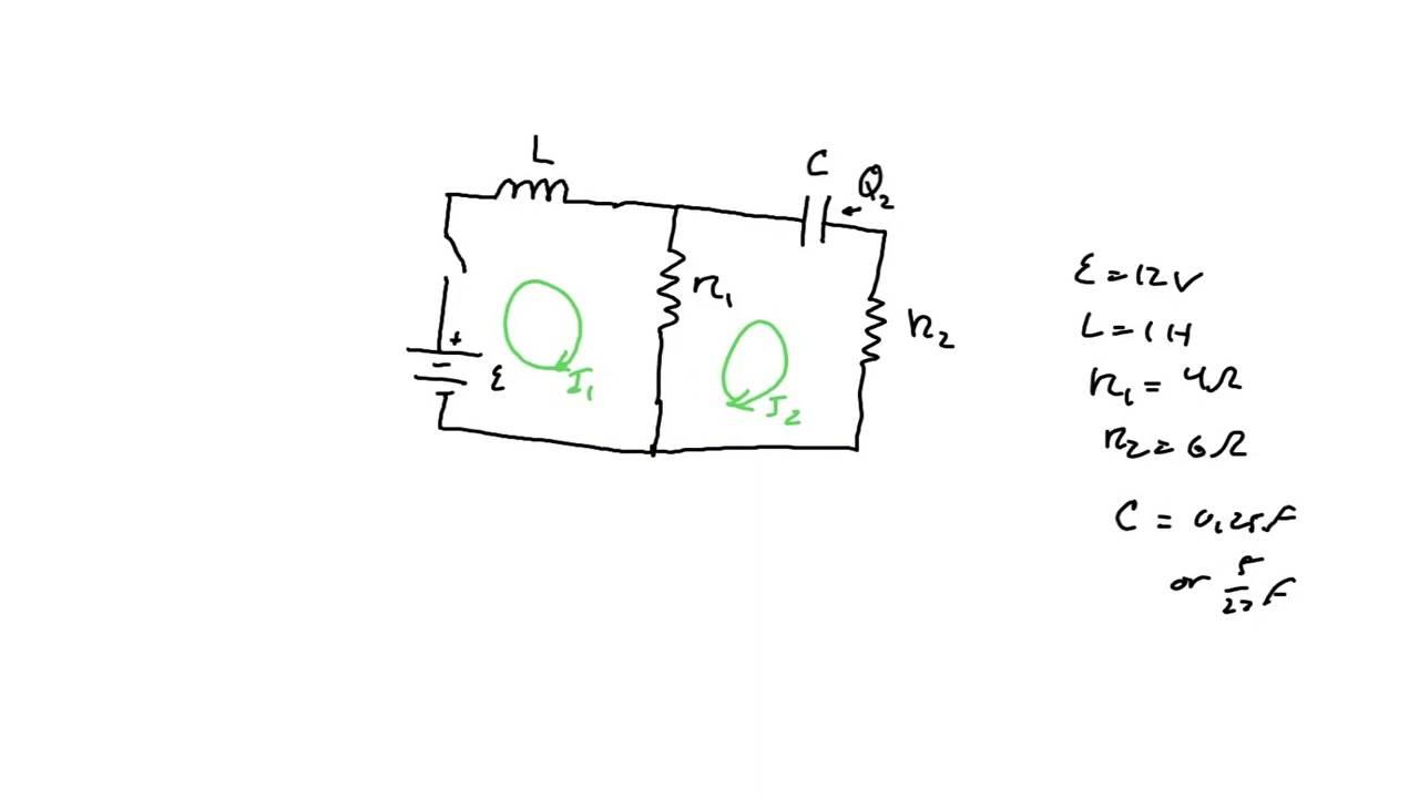
https://www.chegg.com/homework-help/questions-and-answers/let-1-t-2-t-currents-network-figure–assu…
https://www.chegg.com/homework-help/questions-and-answers/let-1-t-2-t-currents-network-figure–assu…
Related image with solved for the network shown in the figure find the chegg com


 | Chegg.com")

 | Chegg.com")
 | Chegg.com")
 | Chegg.com")
 Find The | Chegg.com")
 The | Chegg.com")


Related image with solved for the network shown in the figure find the chegg com


About "Solved For The Network Shown In The Figure Find The Chegg Com"
Comments are closed.