
Substation Single Line Diagram
Substation Single Line Diagram This technical article describes single line diagrams of two typical power substations 66/11 kv and 11/0.4 kv and their power flow, principles of incoming lines (incomers) and outgoing lines (feeders), busbar arrangement functionality and so on. In this article, we’ll take a look at what a substation one line diagram is, how it’s arranged, and the types of information it conveys. we’ll also provide some tips for understanding and interpreting this type of diagram.
 | Bibliocad")
Electrical Substation Single-line Diagram (85.17 KB) | Bibliocad
Electrical Substation Single-line Diagram (85.17 KB) | Bibliocad Here in this article, we will discuss what is single line diagram in a substation, various symbols used in single line diagrams to represent components, and what is the purpose of a single line diagram. Now we shall see an example of a single line diagram of an 11kv/400v indoor substation and its explanation. the utility taps the 3 phase, 3 wire 11 kv line and brings it to the gang operating switch installed near the substation. The single line diagram of an 11 kv substation is shown in the figure below. the single line diagram makes the system easy and it provides the facilitates reading of the electrical supply and connection. The document discusses single line diagrams of substations. it explains that substations receive power from generating stations at high voltages and reduce the voltage to suitable levels for transmission and distribution.

Single Line Diagram Of Electrical Substation
Single Line Diagram Of Electrical Substation The single line diagram of an 11 kv substation is shown in the figure below. the single line diagram makes the system easy and it provides the facilitates reading of the electrical supply and connection. The document discusses single line diagrams of substations. it explains that substations receive power from generating stations at high voltages and reduce the voltage to suitable levels for transmission and distribution. Learn about the symbols used in a substation one line diagram. understand the meaning and significance of each symbol and how they are used to represent electrical components in a substation. A one line diagram is a graphical representation of a substation’s equipment and how it is interconnected. the primary purpose of the one line diagram is to provide a quick and easy way to see the overall configuration of the substation, as well as to identify specific pieces of equipment. It is the representation of different equipment of electrical systems in a substation with the help of lines and the standard symbol of each equipment. we represent the three phase system with a single line of our substation, so it is called a single or one line diagram. The single line diagram (sld) is the most basic of the set of diagrams that are used to document the electrical functionality of the substation. its emphasis is on communicating the functions of the power equipment and the associated protection and control system.
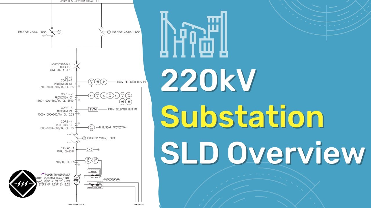
220kV Substation Single Line Diagram (SLD) | Overview | TheElectricalGuy
220kV Substation Single Line Diagram (SLD) | Overview | TheElectricalGuy
Related image with single line diagram of substation

 | Bibliocad")


 | Bibliocad")


Related image with single line diagram of substation
 | Overview | TheElectricalGuy")

 Using These 5 Simple Steps")
 of 33/11kV Substation | Explained | TheElectricalGuy")
About "Single Line Diagram Of Substation"
Comments are closed.